
The CD Format
Understanding the CD-format and other formats at a deepler level, will make it much easier to pursue high fidelity audio playback and recording.
For understanding the CD-format we must first understand PCM.
PCM means "Pulse Coded Modulation" which is a rather stupid and misleading name for what it really does, as there are neither pulses nor modulation present in the process of PCM ;-)
What PCM does
Well, it does two things:
1) A analog signal (which has the attribute to be continuous) is captured by only looking at it from time to time.
If we look at a continuous signal at equally spaced time instants, what we see is only an amplitude: As we look NOW, the amplitude is high. The next NOW-instance (equally spaced) the amplitude is low.
This process is called discrete time sampling. We look at a continuous wave, but only at discrete (and equally spaced) time-points.
The wave is continuous, but our sampling is time-discrete.
2) Every discrete timepoint, we look at the wave signal, we write down the amplitude that is present at this exact timepoint. And now the C from PCM comes into action: We measure the amplitude and write it down as a number. We humans have 10 fingers and so we would use the decimal-code for writing down numbers. The digital technology we invented works with 2-fingers only and therefore when writing down the amplitudes, we have to use the binary-code.
A number-code is a powerful thing!
If I would like to communicate that I want to sell you 100 Apples, I could draw an apple on a piece of paper, and then make 100 dots below the apple, which would be an uncoded value. Then you can count the dots and know, how many apples you are able to buy from me.
Stupid idea, you say ? Right you are. Its a good thing to have a number code, so as a human with 10 fingers I will draw an apple and below the apple I would write 100.
If we would have only two fingers, I would write down the number in binary code: 1100100, and you would certainly know how many apples I mean.
With the aid of a number code, we can save storage space. Instead of making 100 dots for 100 apples, I simply write 100 (decimal) or 110100 (binary).
The real power of the number code comes into action, when larger numbers are to be communicated: Whenever, I add a digit to a binary coded number, I double the expression. When I add a digit to our decmial code system, I am able 10-fold the expression.
3 digits in decimal go up to 100 combinations, 4 digits go to 1.000, 5 digits go to 10.000, wow !!!
1 digit in binary goes up to 2 cominations (1&0), 2 digits go to 4, 3 ->8... 8 digits make up 256 combinations, 16 binary digits go as large as 65536 combinations, wow !!!
Why the shit am I telling you this shit ?
Trust me, you will need that later when we go to explore recent 'other than PCM' formats ;-)
Okay, lets summarize:
PCM is time discrete sampling of a continuous wave and writing down (storing) the amplitude values in a binary coded form.
A much closer expression would be TDAC: Time Discrete Amplitude Coding
But lets just stay with that old PCM.
PCM has exactly Two Parameters
- how fast the sampling
- how high the amplitude resolution
As for the CD-format the parameters are:
- we sample as fast as 44.100 times in a second
- we sample the momentary amplitude as accurate as 16-bit which represents 65536 levels
Wow, that's pretty fast and pretty accurate.
Let's take a look at it.
The following diagram shows you a 1kHz sine wave, sampled with CD parameters (16bits, 44.1kHz):
Wow, this looks like a sine wave. It seems that this PCM works pretty well.
Now, what happens, if we pull some throttle and choose to sample a higher frequency sine, let's say 6 kHz:
Okay, with 6kHz, we have 6-times less sample points per wave-period, compared to 1kHz, so the 6kHz wave looks a little coarse, as one wave is sampled at only 8 discrete timepoints. But hey, if we smooth out the squares with some kind of filter, it will come very close to a real sine.
So let's stay optimistic and further increase the frequency of our sampled sine wave to14kHz
Err, this looks strange. Does this look like a sine wave? There seems to be some real strong amplitude modulation. Is this the M of PCM ? Certainly not after its inventor ;-)
As you see, there are less than 4 sample-points per wave-period. How can we guarantee, that when we sample, we always get the highest and lowest point of the wave ? Well, actually we cannot, as our sampling-frequency of 44.1kHz is not synchronized to our sine wave and we have so few sampling-points per wave.
However, we still see that there is a 14kHz wave, but its volume (amplitude) has been modulated by a lower frequency of about 2kHz. Let's call this a beat-frequency.
- To make thinks even stranger, the above recording looks as if a second tone has been added.
In fact, we always get that beat-frequency with any sampled wave that is not exactly a whole division of the sample-rate. So we expect no beats with 22.05 kHz, 14.7kHz, 11.025 kHz, 8820Hz, 7350Hz, 6300Hz, and so on.
Let's give that a try and take a look at 14.7kHz
Yes. There's no beat to see. All exactly the same amplitude.
But what happened to the waveform? This looks more like a sawtooth than like a sine-wave.
Well, with exactly 3 sample points per wave-period, it cannot be any other way.
Above and below any whole division of the sample-rate we get beats. The higher the frequency (or the lower the available sample-points per wave-period) the higher the amplitude of the beat. From app. 18kHz on we got a beat (amplitude-modulation) of 100%.
So this is 18kHz:
You can hardly tell, what this one wants to be. However, as our recorded frequency approaches the next whole division of the sample-rate, the beat frequency slows down. Look at 20kHz:
This has a 4kHz beat with 100% amplitude modulation.
The following is 21kHz:
The beat frequency goes down to app. 2kHz.
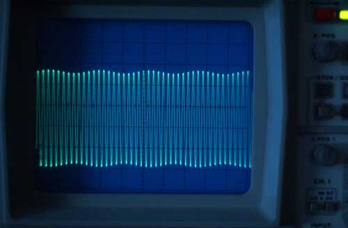
When we increase the frequency of our sampled-sine to 22kHz, we get a real slow beat:
Let's step back a little:
Wow, a 22kHz sine wave, sampled with the CD format of 44.1kHz results in a sine wave with a 100Hz beat.
As a matter of fact, this does not only happen when we sample very high-frequencies, but with every frequency that approaches a whole division of the sample-rate. For lower frequencies we just have a lower amplitude-modulation.
Yes, But ... err... Nyquist ...eeh ...
Well, what did Nyquist say ?
maximum data rate in a noiseless channel = C = 2*W log base2( L ) bits/sec
* where 2W is 2 times the highest frequency contained in the noiseless channel, and
* where L = number of discrete levels (e.g., binary = two levels, 0 and 1)
As Nyquist seems to have been more interested in data transmission than in high-fidelity, we should not wonder, that his statement just defines a maxiumum data-rate of a communications channel.
If we consider the presence of a frequency in a communication channel to be a piece of information, we can agree, that we need twice the sampling rate in order for this frequency to show up. And as we see in the above diagrams, although those signals can look awful, the frequency 'as an information' shows up.
Later, Claude Shannon said:
If a function s(x) has a Fourier transform F[s(x)] = S(f) = 0 for |f| > W, then it is completely determined by giving the value of the function at a series of points spaced 1/(2W) apart. The values sn = s(n/(2W)) are called the samples of s(x).
This goes much further than Nyquist's words, in that it states, that a signal which consists of sine waves with a maximum frequency of W is completely described by recording its values twice as fast as W.
The real cool thing is that Shannon also gave a interpolation formula to get back to the original signal:
Unfortunately this formula includes an infinite sum... What does that mean ?
Well, it means at least one thing:
If we do not take into account infinite samples, we cannot get exactly back to the original signal !
Now you know the true meaning of the sampling theorem. It means, you never get back to exactly the original signal, in finite time :-)
Funny enough, it is said to be a consequence of the sampling theorem, that a signal cannot be bandlimited AND timelimited. If a signal is 100% bandlimited, it cannot be timelimited anymore. If it is timelimited, it cannot be bandlimited.
The first prerequisite of Shannon's sampling theorem is that the Fourier transform or the input signal is zero for all signal frequencies above half of the sampling frequency. That means that the input signal must be 100% bandlimited, which at the same time means, it cannot be time-limited anymore, and therefore infinite samples would be needed in order to exactly reconstruct it.
If this 100% bandlimit is not exercised prior to sampling, we will get what is called alias distortion. Alias distortion means, that more than one input signal is able to generate the same samples, and then the samples do not describe an identical signal, but a variety of signals (including the aliases).
If we do not 100% bandlimit the input signal prior to sampling, we cannot get exactly back to it !
Of course it is not possible to realize a 100% bandlimit during recording. Therefore we will always get at least some small amount of alias distortion.
Please note, that all of the above green diagrams were constructed from mathematically pure sinwaves which are 100% bandlimited and infinite. So we have met the bandlimit criterion. But why do some of them look so bad, and how can we get back to the original sines ?
The green diagrams show just the samples taken. You will get the same picture if you play those samples with an ideal R2R DA converter that has infinitely fast slew rate and infinitely short settling time and infinite precision (conditions we can never achieve in reality).
Now theory says, that if we run that stair signal to an ideal low-pass filter (with a infinitely sharp transition at half the sampling frequency), we will get back to one exact input signal, which is the original pure sine in this case.
An ideal lowpass filter has a step response that is infinite.
Guess what I'm talking about ?
There a damn much infinities involved in this game of sampling.
What about Oversampling ?
Oversampling is an attempt to make use of Shannon's interpolation formula, in order to get the beat frequencies (alias) out of the sampled signal (that we interpret as correctly recorded samples).
As Shannon's formula requires infinite calculation, an oversampling filter has to work with something that take less time than infinity.
As a result, the outcome is less than perfect. The beats are reduced the more, the sharper the filter works and the longer it rings... It is actually the ringing that bridges the beats.
You may take a short excursion to Time or Band in order to see, how the step response of a lowpass filter reconstructs a sampled signal.
With the DF1704 digital filter which has a stopband attenuation of -115dB, I was able to recognize beat-products starting to appear at about 14kHz, with a simple analog oscilloscope.
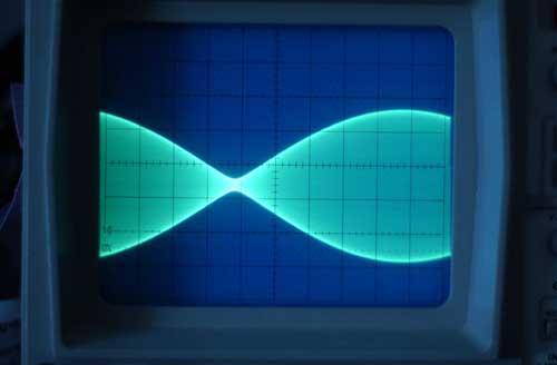
The following scope-shot is 21kHz and shows a real-world beat:
You may download this 21kHz tone by clicking here.
If we compare that to the 21kHz sample-diagram above, we realize, that the oversampling filter was able to reduce the beat amplitude. This is possible if the beat goes over few cycles of the sampled wave. If the beat frequency becomes slower, the oversampling filter is less able to filter it away.
Just as in the following measurement of 22kHz:
You may download this 22kHz tone by clicking here.
This looks very similar to the 22kHz diagram above. Note that the beat frequency can become infinitely small, as the sampled sine wave approaches a whole division of the sample-rate. This implies that the interpolation filter must process infinite samples at the same time, and it must ring eternally.
Adding to the confusion is the fact, that DA converter designs, that employ less or no oversampling at all (that play all the beats undiminished), ususally can sound very good (more musical). This is believed to be related to the absense of filter ringing in a non-oversampling design.
Is PCM a Tremolo Machine ?
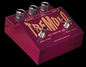
In a way, you can say that our imperfection to meet the infinite requirements to exact sampling and filtering make PCM a complex tremolo machine with a variety of Speed and Level knobs.
A tremolo machine is an effects device that modulates the volume (loudness) of an input signal.
With the Speed knobs, you determine the speed of the tremolo effect and with the Level knobs you can adjust how much of that effect will be operated on the signal.
The closer the sampled frequency comes to a whole division of the sample-rate, the slower the beat frequency.
The Level knob of PCM seems to work in ranges that are determined as follows:
How many sample-points are available for sampling a single wave period ?
If we have between 2 and 3 sample points (14.7kHz .. 22.05kHz), the tremolo level is high (up to 100%).
If we have between 3 and 4 sample points available for a single wave period (11.025kHz .. 14.7kHz), we have up to 50% tremolo level.
For 4 to 5 sample points per wave-period (8.82kHz .. 11.025kHz) tremolo Level goes further down to about 25%.
It seems, that each time we add one sample point to a wave-period, the tremolo level is cut in half.
That means that for frequencies as low as 1 tenth of the sample-rate, the tremolo level is below 1%.
And now... What can We do About it ?
Let's take a real close look at a simple 14kHz sine wave recorded with the CD format:
How can we improve that one ?
What about going from 16 bits to 24 bits resolution ?
Okay, lets try this out. See below the same recording done with 24 bits:
Oops, that looks pretty much the same as the first one. How can it be any other way ? With 16 bits we already have an amplitude resolution of 65536 steps, which is something like ... Wow ...
Okay, despite the fact that a true 24-bit recording is well beyond reality (more on that later), that idea did not bring us any further at all.
What about increasing the sample-rate ? Okay, lets try it out with twice the speed. See below 14kHz sampled with 88.2kHz:
Oh yeah, that is a much better reminder of a sine wave. Let's add some filters to smooth out the edges, and we have made real progress.
Now, as storage place becomes cheaper and cheaper each day, why not doubling the sample-rate again?
See below 14kHz, sampled with 176.4kHz (just 4-times the CD-sampling-speed):
Man, I like that one. That's music to my eyes ;-)
My opinion goes like this:
- We can have higher fidelity with 16 bits amplitude resolution and 10 or more sample-points per wave-period, as we can recover the original signal with a very small amount of beat products (less than1%).
As we cannot meet all those infinity requirements of exact sampling according to Shannon in the real world, and because of those issues that the sharp filters do not necessarily sound best to our ears, we can loosen all those sharp conditions by just sampling faster.
And then we can achieve better sound quality in reality, not just on the paper !
Altmann Micro Machines … Dipl.-Ing. Charles Altmann… Erlenstrasse 15… 42697 Solingen… Germany
phone +49-212-233-7039… email
- Other Altmann Sites: www.jitter.de www.altmannhaan.de www.ammhaan.de
- AMM reserves the right to make changes without further notice to any products herein to improve reliability, function or design.